Original post written by Giuseppe Natalini on 30th March 2022

In previous posts (see the ones written on 08/01/2022 and on 21/01/2022) we have discussed the aspects of the image you can see in Figure 1 which have attracted ventilab readers’ attention. Today we are going to discuss the points that attracted my attention as I was walking in front of the patient’s monitor, and that made me stop to analyze and solve an obvious issue. We are therefore going to try and systematically analyze the problem, which has also been detected by some readers.

As you can see in Figure 2, the inspiratory flow peak (0.97 l/s) is more than twice as big as the expiratory flow peak (0.42 l/s).
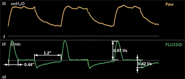
Tidal volume inspiration (which coincides with the presence of inspiratory flow during the inspiratory time) is completed very fast, using only the first 0.44 seconds of the 1.2 seconds which make up the inspiratory time. On the contrary, the whole expiratory time (1.2 seconds, the same as inspiration), is not sufficient to zero the expiratory flow. In other words, during inspiration we can sense the presence of a really low time constant (“fast inspiration”) while during expiration we can sense the presence of a really high time constant (“slow expiration”). (you can find previous posts on the time constant here -available only in Italian, at the moment -: 30/06/2016, 17/07/2016 and 05/02/2014).
This is a truly abnormal behavior during pressometric ventilation, since we would expect the inspiratory and expiratory flow peaks to have a similar amplitude (or the expiratory flow peak to be higher than the inspiratory one in case of autoPEEP), and a similar shape of the inspiratory and expiratory flow curves (in absence of flow limitation).
The coexistence of a “fast” inspiration and a “slow” expiration can be explained either by a big difference between inspiratory and expiratory resistance or by the presence of flow limitation (you can see the post on flow limitation written on 04-06-2012, -available only in Italian, at the moment -). In this case, we can reasonably exclude the presence of flow limitation since the expiratory flow has a normal exponential decay.
The only possible explanation is a significant difference between inspiratory and expiratory resistances. These resistances include both the patient's airway resistance and the respiratory circuit’s resistance.
In Figure 2 we saw that the expiratory flow peak is less than half as big as the inspiratory flow peak: since flow is inversely proportional to resistance, expiratory resistance is more than twice as big as inspiratory resistance, and it would make little sense to attribute this condition to the airways.
We therefore can deduce that there must be an additional expiratory resistance which does not belong to the patient.
And this is true in our case: as sometimes (or often, depending on habit) happens is Intensive Care Units, an antibacterial HME (Heat and Moisture Exchanger) filter was positioned at the end of the expiratory branch on the respiratory circuit in order to protect the expiratory valve from possible contaminants present in the exhaled air.
The problem is that HME filters are made specifically to absorb humidity, and they can be useful in this sense if they are placed on the circuit’s Y: they accumulate expired humidity and give it back to the patient immediately during inspiration.
When an HME filter is placed on the expiratory branch, it absorbs any eventual excess humidity (it’s its job!), and, by “getting soaked in water”, it becomes an additional resistance between the patient and the ventilator’s expiratory valve. A resistance which is entirely expiratory.
Let’s try to better understand this mechanism by looking at Figure 3, which shows the ventilator’s circuit: the INSP branch brings the flow of gas from the ventilator to the patient and the ESP branch brings expiratory flow on the outside, by making it pass through the ventilator’s expiratory valve (shown in red).

The HME filter put on the expiratory branch in order to protect it from possible contaminants is shown in green.
During expiration, the expiratory valve continuously regulates its opening against flow in order to maintain, at its entrance, the same pressure as set PEEP.
If the HME filter at the end of the expiratory branch becomes a significant resistance, the pressure above the HME filter (towards the patient) will be significantly higher than the one below the filter (towards the expiratory valve).
In this condition, the expiratory valve continues to modulate pressure in the section between itself and the HME filter, but it is insensitive to pressure above the HME filter (between the HME filter and the patient), which therefore is determined by HME filter’s resistance and not by the expiratory valve.
The patient will have an expiratory pressure much higher than set PEEP, which will become an obstacle to expiration.
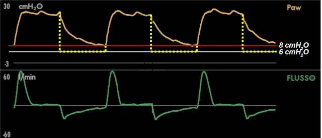
In Figure 4 you can see the difference between PEEP, set at 6 cmH2O (horizontal gray line) and the real pressure during expiration, which, even at the end of expiration, does not reach the set value and stops at a PEEP of 8 cmH2O (horizontal red line). The dashed yellow line show the ideal pressure that should have been present during expiration, i.e. an immediate transition from inspiratory pressure to PEEP: we can hypothesize that, in the portion of circuit between HME and the expiratory valve, pressure was very similar to the own shown by this line.
Proof that, in our case, this was the correct interpretation of what was happening was given by eliminating the HME filter from the expiratory branch. The immediate result can be seen in Figure 5.

At a glance, it is completely different from the image in Figure 1: the crude differences between inspiration and expiration have disappeared. We can confirm this by measuring inspiratory and expiratory flow peaks and duration of flow during inspiration (Figure 6).

There are still some small differences left, which are hard to find without measurement, and which are absolutely compatible with normality.
The problem we have described can have unfavorable implications for patients. In our case, it did not cause any problems, giving only an autoPEEP of 3 cmH2O (measured with an end expiratory occlusion) in a sedated and paralyzed restrictive patient.
But let’s think about an obstructive patient during assisted ventilation. The obstacle to expiration and the resulting worsening of dynamic hyperinflation would produce an increase in the work of breathing associated with a lesser diaphragm efficiency due to the flattening of the muscle caused by an increased end expiratory lung volume. In other words it could iatrogenically perpetuate the dependency from mechanical ventilation in patients with the potential to be weaned from it.
Considering the risks we have seen, is it the right thing to put a HME filter on the expiratory branch? Do benefits outweigh risks?
In my opinion, no filter is needed if inhaled gas humidification and administered inhalation therapies are carried out correctly. During administration of inhalation drugs, it could be better to use a pressure trigger in order to limit the effect of continuous flow with a flow trigger (see the post written on 22/05/2011 -available only in Italian, at the moment -), which could favor the passage of the drug from the delivery point to the expiratory valve.
If humidification and drug administration are not carried out correctly, the solution is to improve the way they are performed, not to use a filter. In case of inappropriate humidification, applying a filter to protect the ventilator perpetuates the problem of excessive humidification. If drugs end up in the expiratory branch, using a filter perpetuates the fact that part of the drug which should reach the patient would be “wasted” in the filter: the only real solution is a correct administration of the drug.
I realize that, sometimes, a filter on the expiratory branch is the lesser evil, or that the filter can have the theoretical role of avoiding environmental contamination with pathogens: in these case, it might be better to use a non-HME filter, keeping an eye on flow and pressure curve monitoring in order to recognize immediately the moment when the filter needs to be changed.
Let’s check the numbers…
In this section we are going to quantitatively analyze what we have just described, making a small exercise in respiratory mechanics. Don’t worry if you are not interested in this discussion (with calculations and formulae): you can jump directly to the conclusions.
In Figure 7 you can see the curves with a series of values recorded during inspiratory and expiratory flow peaks.

Compliance.
First of all, we can calculate Compliance (C), thanks to the fact that a constant inspiratory pressure is associated with a period of no airflow during more than half of the inspiratory time: this is, to all effects, a plateau pressure (Pplat). The total PEEP (PEEPtot) was measured during an end expiratory occlusion: I have recorded its value (9 cmH2O ) on Figure 7. The difference between Pplat (25 cmH2O ) and PEEPtot is the elastic pressure (Pel): 16 cmH2O.
Compliance, i.e. the ratio between tidal volume corrente (225 ml) and Pel, is 14 ml/cmH2O .
The compliance value will let us estimate Pel at different lung volumes, since Pel is always the ratio between volume (V) and compliance (V/C). The alveolar pressure (Palv) is always the sum of Pel and PEEPtot.
Resistive pressure and resistance during the inspiratory flow peak.
Flow is alway generated by a pressure difference, also called resistive pressure (Pres).
The Pres that generates inspiratory flow peak (PIF) is the difference between airway pressure (Paw) when there is the PIF (25 cmH2O, in this case equal to Pplat) and Palv at the same time.
During the PIF, the lungs contain 116 ml of volume (above the end expiratory lung volume), which determines, in that instant, a Pel of 8 cmH2O (V/C). Adding Pel to PEEPtot, we can estimate a Palv of 17 cmH2O.
PIF’s Pres is the difference between Paw and Palv: 25 cmH2O - 17 cmH2O = 8 cmH2O .
Resistance is calculated as the ratio between Pres and the flow it generates. Resistance during PIF is therefore: 8 cmH2O / 0.97 l/s = 8 cmH2O·l-1·s.
Resistive pressure and resistance during the expiratory flow peak.
Repeating the same calculations for the expiratory flow peak (PEF), we can estimate a Pel during PEF of 14 cmH2O, generated by 190 ml of volume which are still in the lungs at that time. Adding it to PEEPtot we obtain a Palv during PEF of 23 cmH2O.
PEF’s Pres is 3 cmH2O, i.e. the difference between 23 cmH2O (Palv) and Paw during PEF (20 cmH2O, Figure 7). Resistance during PEF is therefore: 3 cmH2O/ 0.42 l/s = 7 cmH2O·l-1·s.
The fact that inspiratory and expiratory resistance (calculated during the respective flow peaks) are similar (8 and 7 cmH2O·l-1·s, respectively) confirms that the difference between expiratory and inspiratory resistance is not due to the patient. In fact we have made our calculations using a pressure of 20 cmH2O during PEF which the ventilator obviously measures before (above) the HME filter. Figure 8 can help to better understand this explanation: inside the light blue circles you can read the pressure found in different point at the time of the PEF, in the gray squares on the right the pressure differences between the different points.

The HME filter creates a resistance to flow which can be measured if pressure difference above and below the filter itself is known. Above the filter, during PEF, we have a measured pressure of 20 cmH2O, below the filter we can estimate we have a pressure equal to the set PEEP (6 cmH2O), which the expiratory valve should maintain throughout the entire expiration.
The filter’s Pres during PEF is therefore 14 cmH2O, which, with a flow of 0.42 l/s, let’s us calculate a resistance of 33 cmH2O·l-1·s.
During expiration, the patient must overcome both his own resistance (7 cmH2O·l-1·s) and the filter’s resistance (33 cmH2O·l-1·s), which equals, in total, 40 cmH2O·l-1·s: an enormous resistance, mostly (83%) due to the HME.
For this reason the presence of the filter is the root of the problem, and its removal is the solution.
Conclusions.
Let’s try to summarize the main points illustrated in this post:
Graphical waveform monitoring detects problems (even severe ones) which are not detected by ventilator alarms: only the analysis of pressure and flow curves let us make the correct diagnosis and solve the problem immediately;
The need to use filers on the ventilator circuit’s expiratory branch is conditioned by an inadequate airway humidification and/or inefficient administration of inhalation drugs. In these cases the primary solution should be the optimization of humidification and drug delivery, instead of placing a filter to protect the expiratory valve;
In case the placement of a filter at the end of the expiratory branch is deemed necessary, it might be better to chose an antibacterial/antiviral non-HME filter and to keep an eye on pressure and flow curves ensuring that:
expiratory pressure rapidly returns to the set PEEP value at the start of expiration;
During pressometric ventilation, the shape of inspiratory and expiratory flow are similar in passive patients without flow limitation.
As always, a smile for all the friends of ventilab.